


Think electricity is safe until it isn’t? An arc flash can reach about 35,000°F, roughly four times the surface of the sun.
It’s a sudden, explosive release of electrical energy that vaporizes metal, throws molten shrapnel, and burns skin in milliseconds.
This post explains what causes arc flashes, how incident energy and the arc flash boundary translate into real danger, and which steps actually reduce risk on site.
Read on to learn how to prevent, measure, and repair the damage so workers go home safe.
Core Concept Breakdown: Understanding an Arc Flash Hazard

An arc flash is a sudden, violent release of electrical energy through air when current jumps between conductors or from a conductor to ground. This isn’t some gentle spark. It’s an explosive event that creates a fireball of superheated plasma, molten metal droplets, and a pressure wave powerful enough to knock workers off their feet. The arc forms when something breaks down the normally insulating properties of air, creating a low resistance path that allows thousands or tens of thousands of amperes to flow in a fraction of a second.
The physical effects are immediate and extreme. Temperatures at the arc core reach approximately 35,000°F, roughly four times hotter than the surface of the sun. That heat vaporizes metal conductors, ignites nearby materials, and burns exposed skin in milliseconds. The arc also emits blinding ultraviolet and infrared light that can damage eyes. The explosive expansion of air and vaporized metal creates a pressure blast with sound levels exceeding 140 decibels. All of this happens faster than a person can react.
Incident energy is the measure that determines how dangerous an arc flash will be at a given distance. It’s expressed in calories per square centimeter (cal/cm²) and represents the thermal energy delivered to a surface. A threshold of 1.2 cal/cm² is commonly used to define the arc flash boundary, the distance at which an unprotected person could suffer a second degree burn. Higher incident energies mean more severe burns, wider hazard zones, and more robust protective equipment required. Understanding incident energy is essential because it translates abstract electrical faults into concrete safety decisions: how far to stand back, what clothing to wear, and whether the work can proceed at all.
Detailed Look at Arc Flash Causes and Contributing Factors
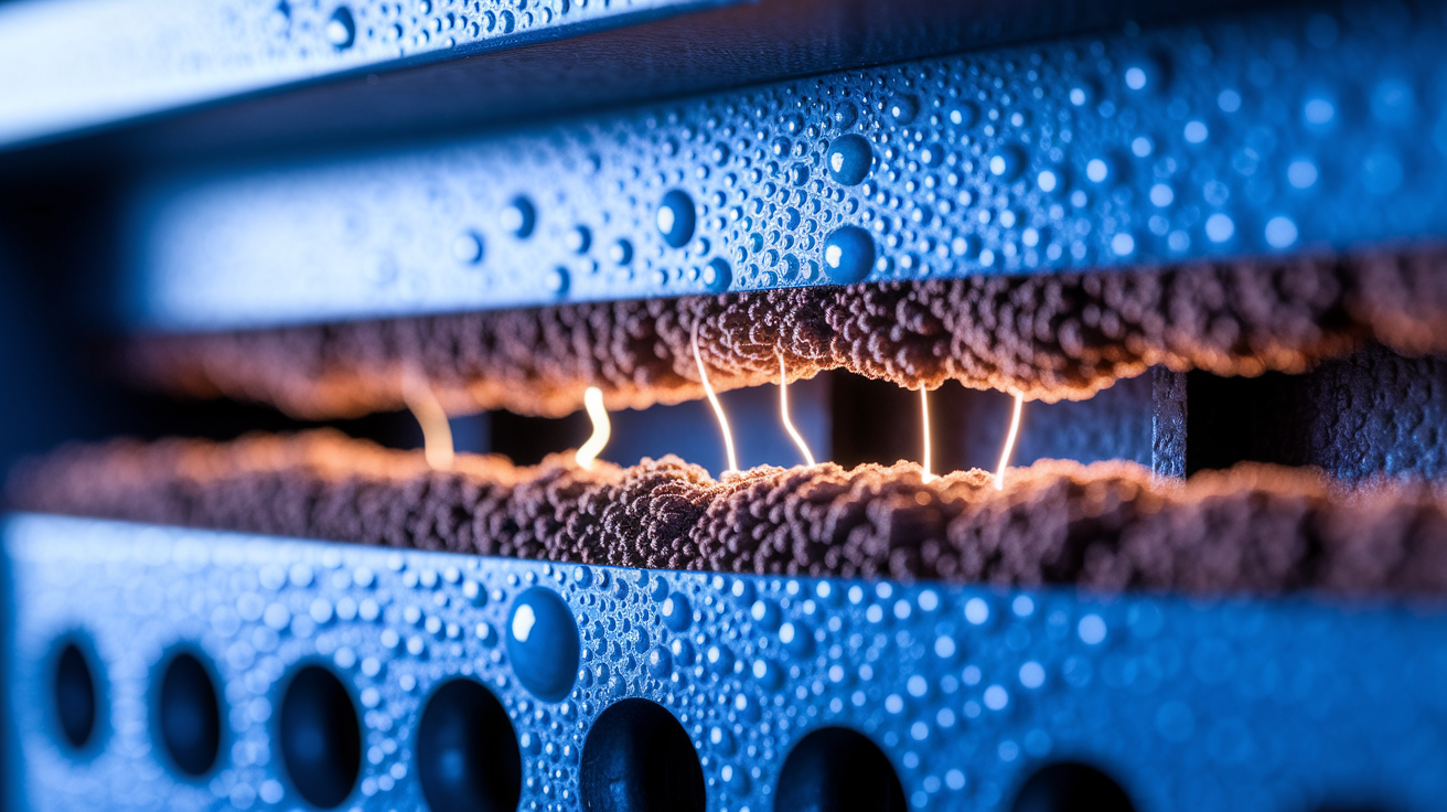
Arc flashes don’t appear out of nowhere. They’re the result of a fault condition, an unintended electrical path that allows current to flow outside its designed circuit. These faults typically occur when insulation fails, conductive objects bridge live parts, or equipment degrades to the point where air gaps can no longer prevent breakdown. Voltage stress, mechanical wear, and thermal cycling all contribute to the gradual weakening of insulation and connections. When the breakdown finally happens, the available fault current in the system determines how violent the arc will be.
Environmental factors make arc incidents more likely. Dust and dirt can settle on bus bars and terminals, creating conductive layers that encourage tracking and flashover. Corrosion eats away at protective coatings and connection points, raising resistance and heat. Moisture and condensation bridge gaps between conductors or compromise insulation, especially in outdoor switchgear or humid environments. Even a small amount of moisture on a contaminated surface can trigger an arc.
Six specific contributors frequently show up in arc flash investigations:
Conductive dust or debris that accumulates inside enclosures and creates low resistance paths. Corrosion on terminals, bus bars, and fasteners that weakens electrical connections. Condensation or moisture intrusion from weather, humidity, or failed seals. Worn, damaged, or improperly rated components such as cracked insulators or undersized breakers. Human error including dropped tools, accidental contact with live parts, or incorrect switching sequences. Lack of preventive maintenance allowing loose bolts, oxidized connections, and degraded insulation to go undetected.
Arc Flash Hazard Effects on People and Equipment
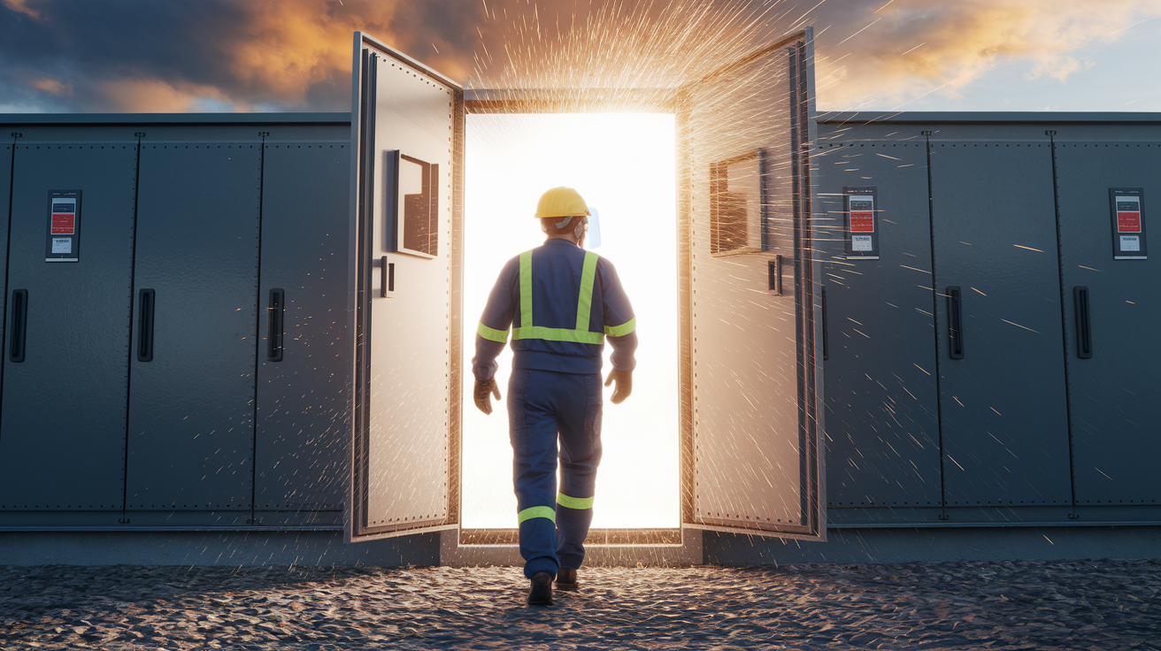
The injuries from an arc flash are severe and often life changing. Thermal burns are the most common, with temperatures high enough to ignite clothing and melt skin in less than a second. Burns can be second or third degree, covering large areas of the body even several feet from the arc. Radiant energy from the flash can burn exposed skin and eyes without direct contact, and the intense ultraviolet light can cause flash blindness or permanent retinal damage. Workers report seeing the afterimage of the arc for hours or days.
The pressure wave, sometimes called the arc blast, adds blunt force trauma to the thermal injuries. The explosive expansion of superheated gases creates a shock wave that can throw a person across a room, rupture eardrums, collapse lungs, or cause traumatic brain injury. Flying molten metal and shrapnel from destroyed equipment become projectiles. Panels blow off their hinges, and metal fragments embed in walls, ceilings, and human tissue. Acoustic energy alone can exceed 140 decibels, causing immediate and permanent hearing loss. Inhalation of vaporized metal fumes and burning insulation adds toxic exposure to an already deadly event.
The worst physical outcomes from arc flash incidents include severe full thickness burns requiring skin grafts and months of recovery, permanent vision or hearing loss from light intensity and acoustic trauma, and fatal cardiac arrest from electrical shock traveling through the body during the fault.
Equipment damage is often total. The heat vaporizes copper and aluminum conductors, leaving behind charred remnants and clouds of conductive soot. Insulation on cables and bus bars disintegrates, and plastic components melt or catch fire. Circuit breakers and relays may be destroyed before they can interrupt the fault, and the pressure wave can warp metal enclosures, crack circuit boards, and contaminate sensitive electronics throughout the facility. Repairing or replacing a damaged switchgear lineup can cost tens of thousands to hundreds of thousands of dollars. The downtime required for investigation, cleanup, and reconstruction often exceeds the direct repair costs.
Incident Energy, Boundaries, and Measured Arc Flash Hazards
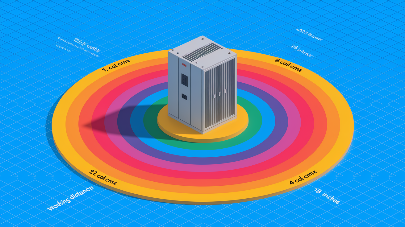
Incident energy is the single most important number in arc flash hazard assessment. It tells you how much thermal energy will strike a worker’s body at a specific distance if an arc occurs. The calculation depends on system voltage, available fault current, the time it takes for protective devices to clear the fault, and the distance from the arc source. Higher fault currents and longer clearing times produce higher incident energies. A modern arc flash study uses IEEE 1584 equations to model these variables and produce cal/cm² values at different working distances.
The arc flash boundary is drawn at the point where incident energy drops to 1.2 cal/cm², the threshold for a curable second degree burn on bare skin. Inside that boundary, unprotected workers face serious burns. Outside it, the thermal hazard is below the second degree threshold, though other hazards like flying debris, sound, and light may still exist. Boundaries aren’t fixed. They expand and contract depending on the equipment, the fault level, and how fast breakers or fuses operate. In low voltage panels with slow overcurrent protection, the boundary might extend four or five feet. In medium voltage switchgear with high fault current and slower clearing, it can reach ten feet or more.
| Threshold Level | Incident Energy (cal/cm²) | Typical Risk Description |
|---|---|---|
| Arc flash boundary | 1.2 | Distance where unprotected skin may receive a second degree burn |
| Moderate hazard | 8 | Significant burn risk; multilayer arc rated clothing required |
| Severe hazard | 40+ | Extreme energy; full arc flash suit, face shield, and insulated gloves mandatory |
Standards That Define Arc Flash Safety Requirements

NFPA 70E is the foundational standard for electrical safety in the workplace. It lays out risk assessment procedures, defines arc flash boundaries, specifies PPE requirements, and establishes safe work practices including lockout/tagout and the concept of an electrically safe work condition. The standard organizes PPE into categories based on incident energy or task based tables, and it requires employers to label equipment, train workers, and document procedures. NFPA 70E is updated every three years, and the 2024 edition reflects current best practices for hazard analysis and PPE selection. Employers in industries where workers interact with energized equipment rely on NFPA 70E to structure their arc flash programs and demonstrate compliance.
IEEE 1584 provides the mathematical framework for calculating incident energy and arc flash boundaries. The standard includes empirical equations derived from controlled arc tests, accounting for variables like system voltage, gap between conductors, fault current, and clearing time. IEEE 1584 also offers guidance on equipment configurations, electrode arrangements, and correction factors for different enclosure types. The 2018 edition expanded the model to cover a wider range of voltages and introduced updated formulas for low voltage systems. An arc flash study performed according to IEEE 1584 produces the cal/cm² values and boundary distances that go onto equipment labels and drive PPE decisions.
OSHA doesn’t publish its own arc flash calculation methods, but it enforces general electrical safety requirements under 29 CFR 1910 Subpart S and references consensus standards like NFPA 70E. Employers have a legal obligation to assess electrical hazards, provide appropriate PPE, train workers, and maintain safe working conditions. OSHA citations for electrical incidents often point to failures in hazard assessment, inadequate PPE, lack of training, or missing lockout/tagout procedures. What is arc flash and how can you stay safer?
Key contributions of each standard:
NFPA 70E establishes work practices, PPE categories, boundary definitions, and employer program requirements. IEEE 1584 delivers formulas and data for incident energy calculations and boundary modeling. OSHA regulations create the legal framework and enforcement mechanism for electrical safety in U.S. workplaces.
Arc Flash Risk Reduction Methods Using the Hierarchy of Controls
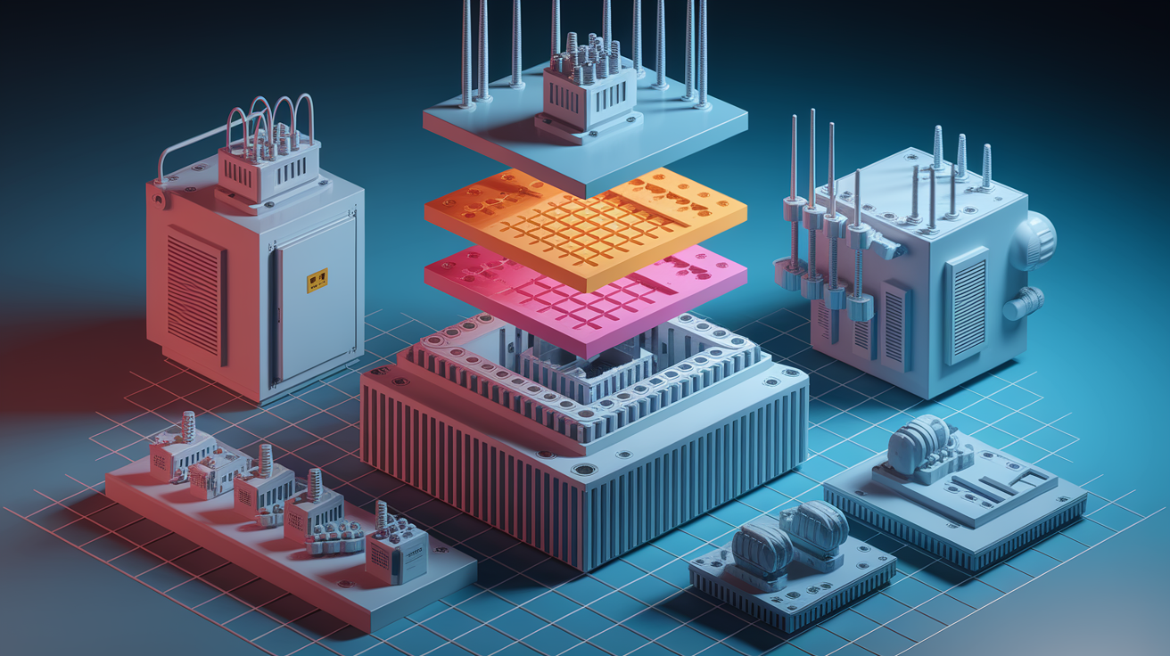
The hierarchy of controls places the most effective protections first and relies on PPE only as a last resort. Engineering controls change the equipment or system to reduce or eliminate the hazard at the source. Administrative controls set rules, procedures, and boundaries that limit exposure. PPE protects the worker when exposure can’t be avoided. All three layers should be in place, but the goal is always to engineer out the hazard before relying on human behavior or protective clothing.
Engineering Controls
Engineering controls physically reduce arc flash energy or remove workers from the hazard zone. Remote racking tools allow operators to insert or remove circuit breakers from outside the arc flash boundary, keeping hands and face away from live bus. Arc resistant switchgear is designed to redirect the energy and pressure of an internal arc away from the operator, venting gases and flame through dedicated channels. Current limiting fuses interrupt faults in less than a half cycle, drastically reducing incident energy. Arc flash relays detect light and current signatures of an arc and trip breakers in milliseconds, cutting fault clearing time and lowering the cal/cm² exposure. Insulated bus systems, better grounding, and proper spacing between phases all reduce the likelihood and severity of arcs.
Administrative Controls
Administrative controls include lockout/tagout (LOTO), work permits, hazard assessments, and documented safe work procedures. The single most effective administrative control is de-energizing equipment and verifying an electrically safe work condition before work begins. When energized work is unavoidable, a written energized electrical work permit documents the justification, the hazards, the required PPE, and the names of qualified workers and supervisors. Training ensures workers can recognize arc flash labels, understand boundaries, select correct PPE, and follow procedures. Scheduling inspections, updating arc flash studies after system changes, and restricting access to electrical rooms all fall under administrative controls.
PPE as Final Protection
Personal protective equipment is the last line of defense when engineering and administrative controls can’t eliminate exposure. Arc rated clothing, face shields, insulated gloves, and hearing protection are selected based on the incident energy shown on equipment labels. PPE must be worn whenever work occurs inside the arc flash boundary on energized parts. It doesn’t prevent the arc, but it can mean the difference between survivable burns and fatal injuries. PPE programs require proper selection, inspection, care, and replacement of worn garments. Workers must understand that PPE protects only if it’s worn correctly, is rated for the hazard, and is maintained in good condition.
Arc Flash PPE Ratings, Clothing Types, and Selection Criteria

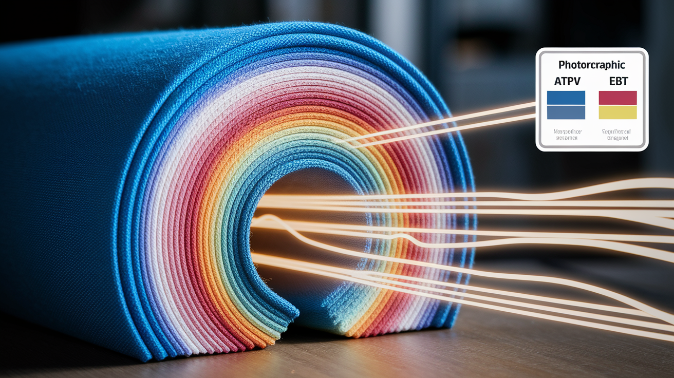
PPE for arc flash protection is rated in cal/cm² based on laboratory testing. Each garment, face shield, glove, and helmet carries an Arc Thermal Performance Value (ATPV) or an Energy of Break Open Threshold (EBT) that represents the maximum incident energy the item can withstand before it fails or allows a second degree burn. Workers compare the incident energy on the equipment label to the ratings on their PPE and choose garments with equal or higher protection. Historical PPE categories, Category 1 through Category 4, correspond roughly to 4, 8, 25, and 40 cal/cm². Modern practice uses the actual calculated incident energy and selects PPE with a matching or higher arc rating.
Arc rated clothing is made from fabrics that resist ignition, don’t melt onto skin, and self extinguish when the heat source is removed. Common materials include treated cotton, modacrylic blends, and aramid fibers. Garments range from lightweight shirts and pants for low energy tasks to heavy multilayer flash suits with hoods and face shields for high energy work. Each layer adds thermal protection, and the total system rating is the sum of all layers worn together. A typical low energy kit might include an 8 cal/cm² shirt and pants. High energy protection often requires a base layer, a coverall, and an outer flash suit, pushing total costs to $1,000 to $2,000 per worker.
Four core PPE components for arc flash protection:
Arc rated shirt and pants or coveralls providing base thermal protection for torso and limbs. Arc rated face shield and hood protecting the head, face, neck, and ears from radiant heat and debris. Insulated leather gloves with arc rated outer protectors to shield hands from heat and electrical contact. Hearing protection and safety glasses to guard against acoustic trauma and flying particles.
ATPV vs. EBT
ATPV and EBT both measure the thermal performance of arc rated materials, but they describe different failure modes. ATPV is the incident energy level at which a fabric transfers enough heat to cause a second degree burn on the skin beneath it, with a 50 percent probability. EBT is the energy level at which the fabric physically breaks open, creating a hole that exposes skin to direct arc energy. Most fabrics fail by heat transfer (ATPV) rather than breakage, so ATPV is the more common rating. When a material’s EBT is lower than its predicted ATPV, the manufacturer reports the EBT instead. For PPE selection, workers use whichever value is listed and ensure it meets or exceeds the incident energy on the label.
Arc Flash Label Requirements and How to Interpret Them
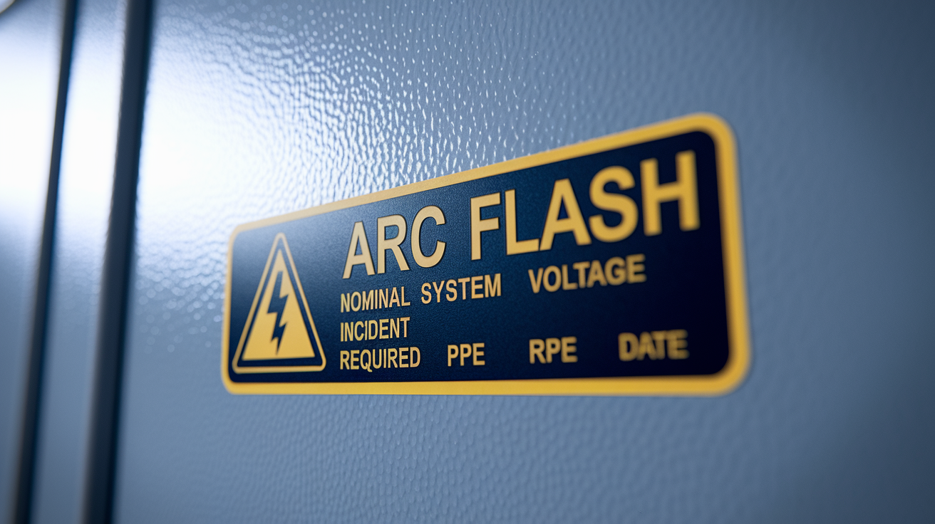
Arc flash labels are the primary communication tool between the arc flash study and the worker in the field. They’re placed on equipment doors, panel covers, and switchgear lineups to identify hazards and required protections before anyone opens an enclosure or performs work. A complete label provides all the information a qualified worker needs to assess the risk, select PPE, and establish safe boundaries. Missing or outdated labels are a compliance failure and a serious safety gap.
Labels typically display the nominal system voltage because higher voltage often correlates with higher fault current and greater arc energy. The incident energy in cal/cm² tells the worker how severe the thermal hazard is at the defined working distance, usually 18 inches for low voltage equipment. The arc flash boundary distance marks the outer limit where unprotected skin could be burned. Some labels list a PPE category (1 through 4), while others specify the minimum arc rating required for clothing and the type of face protection. The date of the arc flash study or the most recent update is included so workers and supervisors know whether the data is current. Any major system change, new transformers, different breakers, added loads, can invalidate the label and require a new calculation.
Five required label elements:
Nominal system voltage to indicate the electrical class of the equipment. Incident energy in cal/cm² at the defined working distance. Arc flash boundary distance beyond which unprotected personnel should not approach. Required PPE either by category number or by minimum arc rating and gear type. Date of the arc flash study so labels can be verified for currency.
Arc Flash Studies: What They Include and When Updates Are Required
An arc flash study is a comprehensive electrical engineering analysis that models the power system, calculates fault currents, evaluates protective device performance, and determines incident energy at every point where workers might perform tasks. The study begins with a short circuit analysis that finds the maximum fault current available at each bus, panel, and motor control center. Next, a protective device coordination study checks whether breakers, fuses, and relays will operate in the correct sequence and time to isolate faults. Finally, using IEEE 1584 formulas, the engineer calculates incident energy and arc flash boundaries for defined working distances at each location.
The deliverables include a one line diagram marked with fault currents and protective device settings, a report documenting assumptions and calculation results, and a set of arc flash labels ready to affix to equipment. The engineer also provides recommendations for reducing incident energy, such as faster trip settings, current limiting devices, or zone selective interlocking. Studies must be updated whenever the electrical system changes. New utility service, added transformers, replaced breakers, load expansions, or when equipment labels become unreadable or are missing. Many facilities update studies every three to five years even without system changes, to align with current standards and verify that protective devices still operate as modeled.
| Step | Purpose | Key Data Needed |
|---|---|---|
| Data collection | Gather system details and equipment ratings | Single line diagrams, transformer nameplates, breaker settings, cable sizes, utility fault data |
| Short circuit analysis | Calculate maximum fault current at each bus | Impedances of transformers, cables, and utility source; system voltage and configuration |
| Protective device coordination | Verify breakers and fuses operate in correct order and time | Time current curves, trip settings, fuse ratings, clearing times |
| Incident energy calculation | Determine cal/cm² exposure and arc flash boundaries using IEEE 1584 | Fault current, clearing time, working distance, electrode configuration, enclosure type |
Training, Worker Qualifications, and Safe Work Practices

Arc flash training begins with hazard recognition. Workers learn what an arc flash is, how it starts, and what the physical effects look like: heat, light, pressure, debris. They study real incident photos and videos that show damaged equipment and injuries, making the abstract risk concrete. Training covers how to read arc flash labels, interpret incident energy and boundary distances, and select PPE that matches the hazard level. Qualified workers also learn the difference between shock hazards and arc flash hazards, and why both must be controlled before work begins.
Hands on practice is essential. Workers demonstrate how to verify de-energization, apply lockout/tagout devices, test for absence of voltage, and don arc rated clothing and face shields correctly. Supervisors review written procedures, energized work permits, and emergency response plans. Retraining should occur at least every three years, or sooner if the worker’s job changes, an incident occurs, or the electrical system is modified. New employees and contractors must complete training before they’re allowed near energized equipment. Documentation of training dates, topics covered, and individual competency assessments is required for compliance.
Four core training topics:
Hazard recognition and arc flash physics including temperature, pressure, incident energy, and boundary concepts. Label interpretation and PPE selection so workers can match protective gear to the cal/cm² rating on the equipment. Safe work procedures covering lockout/tagout, voltage verification, energized work permits, and establishing an electrically safe work condition. Emergency response and first aid for arc flash injuries, including how to shut down equipment, call for help, and provide initial burn care.
Maintenance, Testing, and Inspection to Prevent Arc Flash Events
Preventive maintenance is the frontline defense against arc flash incidents. Loose connections generate heat, increase resistance, and create conditions for arcing. A single loose bolt on a bus bar can raise local temperature enough to degrade insulation, oxidize conductors, and eventually trigger a fault. Scheduled inspections find and correct these problems before they escalate. Infrared thermography scans detect hot spots in panels, breakers, and terminations, revealing issues invisible to the naked eye. Thermography should be performed annually or more often in critical systems, and any temperature rise above baseline warrants investigation and repair.
Electrical testing verifies that circuit breakers and fuses will operate within their rated clearing times. Breakers can drift out of calibration, and contacts can pit or corrode, slowing their response. Time overcurrent testing uses precision instruments to trip breakers at various current levels and measure how long they take to open. If actual clearing time exceeds the value used in the arc flash study, incident energy calculations are no longer valid and must be recalculated. Insulation resistance testing on cables and equipment checks for degradation that could lead to ground faults or phase to phase shorts. Maintenance records, test results, and thermography reports should be kept and reviewed as part of arc flash program audits.
Five item maintenance and inspection checklist:
Torque all bolted electrical connections to manufacturer specifications and re-check annually. Perform infrared thermography scans of energized equipment to detect hot spots and failing components. Test circuit breakers and relays for correct operation and clearing time, comparing results to study assumptions. Inspect insulation and enclosures for cracks, wear, contamination, moisture intrusion, and physical damage. Clean and remove conductive dust, corrosion, and debris from bus bars, terminals, and interior surfaces.
Emergency Response, First Aid, and Post-Incident Investigation Steps
When an arc flash occurs, the first priority is to shut down power if it’s safe to do so and call for emergency medical help immediately. Arc flash burn victims require rapid transport to a hospital with a burn unit. Thermal injuries covering more than a small area are medical emergencies. Don’t remove clothing stuck to burned skin. Cover burns loosely with clean, dry cloth to reduce contamination and heat loss. If the victim is unconscious or not breathing, begin CPR if you’re trained, but be aware that electrical shock may have caused cardiac arrest or internal injuries.
Hearing damage from the pressure wave may not be immediately obvious, and victims often report confusion, disorientation, or temporary blindness from the intense light. Keep the person calm, away from further hazards, and under observation until medical personnel arrive. Document the scene with photos if safe to do so, noting the position of equipment, visible damage, and the location where the worker was standing. Don’t disturb evidence or reset breakers until investigators have assessed the scene.
Three steps for post-incident investigation:
Secure the area and preserve evidence by locking out all power sources, photographing damage, and restricting access until the investigation team arrives. Interview witnesses and the injured worker (when medically cleared) to reconstruct the sequence of events, tasks being performed, and any deviations from procedures. Conduct a root cause analysis to identify equipment failures, procedural gaps, or system conditions that contributed to the arc, then update studies, labels, training, and procedures to prevent recurrence.
Final Words
Sparks jump, light flashes, and a blast pushes out. That’s an arc flash, and it happens in a heartbeat with extreme heat, pressure, and molten metal.
You saw what causes them, how incident energy and boundaries work, the role of standards and labels, and why PPE, maintenance, and studies matter. We covered training, emergency steps, and documentation so you can act with purpose.
This kept arc flash hazard explained plainly so you know what to do next. With the right controls and checks, you can cut risk and get systems back to work.
FAQ
Q: What does an arc flash hazard consist of?
A: An arc flash hazard consists of a rapid electrical discharge that creates extreme heat (up to 35,000°F), intense light, molten metal, and a blast pressure wave that throws shrapnel and hot gases.
Q: What is the 2 second rule for arc flash?
A: The 2 second rule for arc flash treats 2 seconds as a conservative maximum clearing time when device operation is unknown; longer arc duration raises incident energy and greatly increases injury risk.
Q: Who’s responsible for protecting you from arc flashes?
A: The employer or facility owner is responsible for protecting you from arc flashes by assessing hazards, providing training, PPE, labels, and safe procedures; workers must follow controls and supervisors enforce them.
Q: Can you survive an arc flash?
A: You can survive an arc flash depending on incident energy, distance, and protective gear; low-energy events may cause minor injuries, while high-energy arcs can cause severe burns, blunt trauma, or death.